Well I am not sure how deep this Deep Dive is, but I will ensure you for a dummy book this chapter will be deep enough.
Timing Diagram Legends
It is very likely the next material you will read after this one is an AMBA spec, where you will see some timing diagram conventions like below
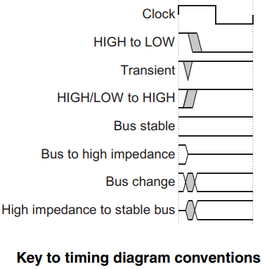
and it will be helpful to understand now what they actually mean.
Well clock is straightforward and you don’t need to be a hardware guy to understand what it means: a high and a low means one clock cycle. The rising/falling edge might trigger some operations in the hardware that driven by this clock (a.k.a Edge Trigger), some hardware could operate when it is actually high/low (a.k.a Level Trigger).
HIGH to LOW basically tells what it is: the signal was high and then turns low. Notice the ‘grey’ area which means there could be some noise / unstable period before it eventually turns low.
Transient, or the ‘grey’ area, again, tells that the signal line(s) is in a transient state and not yet get to a steady state.
HIGH/LOW to HIGH, I bet you can tell me what it means.
Bus stable, means the state of the signal line(s) is steady, one can read from the line(s) and expect valid data.
Bus to high impedance, means the signal line(s) goes into the high impedance, or High-Z state. What it means is that the signal is not driven by any one but instead left open/floating/disconnected. An output pin that connects to this signal will be able to drive it.
Bus change simply means that the data on the bus changes. Again you see some transient state between the two valid data in the bus.
Hi impedance to stable bus means the opposite of Bus to high impedance.
How does APB works
AMBA3 provides the Advanced Peripheral Bus V1.0.
APB provides “a low-cost interface that is optimized for minimal power consumption and reduced interface complexity” (from AMBA 3 APB Protocol Specification).
So we know, APB focuses on low power, and simple interface. With this in mind it would not be difficult to understand:
- APB is for peripherals that are low-bandwidth and do not require high performance, which means transactions via APB will be slow and small-size.
All signal transitions are only related to the rising edge of the clock to enable the integration of APB peripherals easily into any design flow. Every transfer takes at least two cycles.
The APB can interface with the AMBA Advanced High-performance Bus Lite (AHB-Lite) and AMBA Advanced Extensible Interface (AXI). You can use it to provide access to the programmable control registers of peripheral devices.
Let’s now look closer into how data is sent and received via APB:
- Writes. APB has two types of writes: write-with-no-wait and write-with-wait
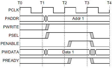
The timing diagram above shows the write-with-no-wait:
The device initiates the write sends the data to an address, and this is what happens on the bus:
- PADDR, the address where the data goes to, becomes available
- PWDATA, the data itself, becomes available
- PWRITE and PSEL are set to high, to indicate this is a write.
OK setting PWRITE is obvious, but what is PSEL doing here? Well APB is a 1-master-n-slave communication model, which means the APB master device sets up the bus communication and also initiates all the APB transactions. The APB slaves only respond to the requests from the master. The APB master has PSEL0, PSEL1 … PSELx pins connected to its slave_0, slave_1, … and slave_x. When the Master sends a request to a slave_n, it sets the pin, PSELn, high, so that slave_n knows there is a request from the master and should respond. A slave device will have only one PSEL pin, and as you could guess, PSEL means PinSELect.
All the three above occur almost at the same time: at the rising edge of the clock cycle T1. And T1 is called the Setup Phase.
After the Setup Phase in the next clock cycle PENABLE will be set at the rising edge of T2, to indicate the beginning of the Access Phase. In the Access Phase the address, data and control signals are guaranteed to be stable and valid for the target of the write to receive the data. After the Access Phase the write operation is complete, which takes 2 clock cycles.
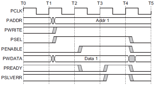
The timing diagram below shows the write-with-wait:
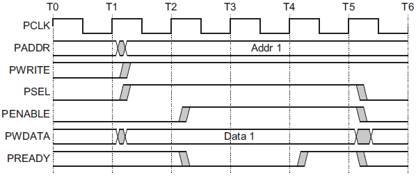
The Setup Phase is the same as the no-wait version. What makes the wait version different is the introduction of PREADY. If the Access Phase needs to be extended, PREADY can be driven low and the other 5 signals/buses will remain unchanged for additional clock cycles, until PREADY becomes high again.
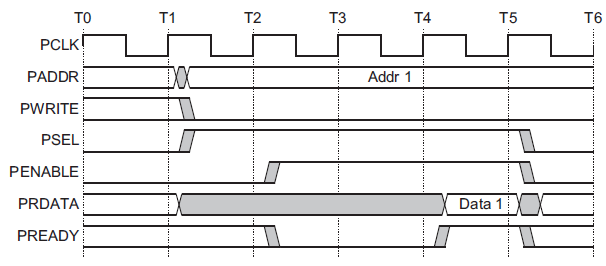
- Reads. Similarly, we have read-with-no-wait and read-with-wait.
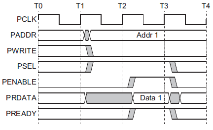
The read-with-no-wait timing diagram is shown as above. It is very similar to that of write-with-no-wait, except that PWRITE needs to be driven low to indicate this is a read. There is the first clock cycle that is the Setup Phase, and the second clock cycle being the Access Phase. PRDATA will be available in the Access Phase since this is a read request.
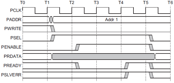
You can guess now read-with-wait will use the same approach as write-with-wait, and yes with PREADY the read can be extended for more clock cycles, as shown in the timing diagram below.
The read-with-no-wait timing diagram is shown as above. It is very similar to that of write-with-no-wait, except that PWRITE needs to be driven low to indicate this is a read. There is the first clock cycle that is the Setup Phase, and the second clock cycle being the Access Phase. PRDATA will be available in the Access Phase since this is a read request.
You can guess now read-with-wait will use the same approach as write-with-wait, and yes with PREADY the read can be extended for more clock cycles, as shown in the timing diagram below
And guess what? You can now run out of your cube and shout “I know how APB works!”
Congratulations. We are moving to the next protocol and I hope to see you there.